shijan Posted February 10, 2017 Share Posted February 10, 2017 Hi there! As you may know i'm a developer of Angle HDMI Clamp Kit http://www.eoshd.com/comments/topic/21377-angle-hdmi-clamp-kit-for-bmmcc-smallrig-cage-and-ugreen-angle-hdmi-adapter/ and co-designer of SmallRig BMMCC cage. My next attempt in this line of projects was the camera handle, but it seems things moving slowly and i decide to release Angle Expansion Box Module first. Box uses high quality connectors made by Lumberg (Germany). It takes months to test a lot of different connectors before choose proper ones, especially DC power which should work smoothly with BMMCC power plug same as with another more simple ones. Angle shape provides compact and secure cable management, no more mess of wires around camera. Fits perfectly to MBAngle HDMI Clamp Kit size and shape. 3D printed body. Compatible with SmallRig and Wooden Camera cages. Compatible with other BMMCC controllers. For request 3.5mm jack can be wired to 2 PWM channels or to S.Bus. Other connectors are 2.5 jack LANC and camera DC power in. Currently this project is in final stage of development. Hope expansion box will be available in month or so. Price will be around $25-$50. Worldwide shipping with registered air mail about $5. Quote Link to comment Share on other sites More sharing options...
webrunner5 Posted February 11, 2017 Share Posted February 11, 2017 Sounds like the price will be nice. Quote Link to comment Share on other sites More sharing options...
mercer Posted February 11, 2017 Share Posted February 11, 2017 I appreciate your efforts with making the BMMCC a more production friendly tool. As you may know I had one last spring/summer and I loved the images I was getting, but the form factor was just a headache for me. Since you are more in the know, regarding accessories for the micro, do you know if anyone has made a hinged plate, so a tilting LCD would be an option for rigging up the Micro? I searched and searched for off the shelf components to make one but could not find anything suitable to the task. With that Ikan 3.5" monitor, and a tilting plate or hinged plate that places the LCD directly behind the micro, I would be very interested in the Micro again. As it is, I am planning on buying a Pocket cam... if BM doesn't release another option at this NAB. Quote Link to comment Share on other sites More sharing options...
shijan Posted February 12, 2017 Author Share Posted February 12, 2017 12 hours ago, mercer said: Since you are more in the know, regarding accessories for the micro, do you know if anyone has made a hinged plate, so a tilting LCD would be an option for rigging up the Micro? I searched and searched for off the shelf components to make one but could not find anything suitable to the task. Yep, I also expect this problem and can't find a solution. I made temporal DIY mount http://www.eoshd.com/comments/topic/20153-the-simplest-bmmcc-rig-ever-made/?do=findComment&comment=163917 Also i co-designed adapter with SmallRig but version to they do it huge and bulky, targeted for heavy monitors http://www.smallrig.com/SMALLRIG-DSLR-Monitor-holder-Friction-Mount-Kits-1842.html i'm tied to prove point of view that people needs more compact things sometimes. Also you can try to DIY experiment with HotShoe or microphone mounts or light stands mounts. People use them as monitor mounts too. Also here is nice stand https://cinegearpro.glopal.com/uk-UA/p-8865859341/dof-micro-cold-shoe-mount-ball-head-for-camera-top-accessory.html?utm_campaign=en_GB&utm_medium=pr&utm_source=www.cinegearpro.co.uk Not sure if it is just rebranded China model something like this https://www.aliexpress.com/item/Camera-Tilting-Bracket-1-4-Screw-Hot-Shoe-Mount-Adapter-for-on-Camera-Led-Video-Light/2038197621.html or https://www.aliexpress.com/item/1-4-Screw-Mini-Hot-Shoe-Ball-Head-Flash-Bracket-Holder-Mount-Screw-For-Camera-Tripod/32605794972.html?spm=2114.30010308.6.7.7hi7J6&s=p or if it is something originally designed Also i don't like that all that mounts are made from plastic. This makes them too shaky even with lightweight monitors. Also you can try to get a metal GoPro mount with 1/4" screw on top if your monitor is really small. Quote Link to comment Share on other sites More sharing options...
shijan Posted February 12, 2017 Author Share Posted February 12, 2017 work in progress . . . Quote Link to comment Share on other sites More sharing options...
shijan Posted February 13, 2017 Author Share Posted February 13, 2017 Currently i search a better way to manufacture a body of the box. At this Sunday my friends made test samples on usual FDM 3D printer and i don't like the results. It appears not too precise and material not strong enough for this kind of small things, also it takes too many time for batch manufacture. So i refuse my idea of simple 3D printed body. Now i got few other more precise and professional manufacture options, like DLP/SLA 3D printers or CNC machined body sample for future molding. Need to test that things too. Also i find a solution for more flexible pinout. Everything will be connected directly to D-sub pins with tiny Dupont Jumpers. Anytime you can just open the box and change pinout for example from S.bus to PWM or to anything you want. Quote Link to comment Share on other sites More sharing options...
tupp Posted February 13, 2017 Share Posted February 13, 2017 You have a nice idea! 2 hours ago, shijan said: Currently i search a better way to manufacture a body of the box. At this Sunday my friends made test samples on usual FDM 3D printer and i don't like the results. It appears not too precise and material not strong enough for this kind of small things, also it takes too many time for batch manufacture. So i refuse my idea of simple 3D printed body. Now i got few other more precise and professional manufacture options, like DLP/SLA 3D printers or CNC machined body sample for future molding. Need to test that things too. Instead of high-end 3D printing or CNC machining, consider silicone molding. You can 3D print a rough master and finish it to your liking, and then make copies of it with the silicone mold. With this method, you have to be mindful that the parts need to be designed to release from the mold, and, of course, you might need plenty of ventilation to safely cure molding compounds. I see a potential problem with your orange part releasing from a mold. Also, don't get too precise with the design/engineering -- in most instances, the precision one thinks is needed is not actually required. Designing with "slop" (sloppy engineering tolerance) is generally a good practice, especially with mating parts and with any manufacturing process that might have shrinkage (injection molding, die casting, extrusion, blow molding, etc.). Design with as much slop as possible, and allow for that slop. It can save you a lot of headaches later on. For your enclosure, it might be good to have about 1/32" (0.8mm) of slop... meaning, for instance, that you should probably design the inner mating surfaces of the orange part to be 1/32" (0.8mm) wider than the outward mating surfaces of the yellow part. Hope this helps. Quote Link to comment Share on other sites More sharing options...
shijan Posted February 13, 2017 Author Share Posted February 13, 2017 Yea, i was thinking about that additional corner too and made some redesign in the evening. It appears that it is not possible to manufacture this with regular CNC machine because there are few triple inner corners which impossible to mill with regular tools. So yes, it will be molded, i have a friend who makes things with same technology every day. Master copy will be 3D printed on hi end printer anyway. Sure it is way more expensive than usual 3D printing, but for one copy it is ok. Quote Link to comment Share on other sites More sharing options...
shijan Posted February 15, 2017 Author Share Posted February 15, 2017 Was testing today different wires thickness and the way to solder them and confirmed that Dupont Jumpers warped with heat shrink tube will fit to VGA pins. Also done a little chart with Lumberg/EST vs OEM China connectors comparison. DC power connectors are also different. I can't find a Lumberg DC power connectors in local stores yet, but already find another brand which is better quality than OEM. Quote Link to comment Share on other sites More sharing options...
shijan Posted February 16, 2017 Author Share Posted February 16, 2017 and all together one more time Quote Link to comment Share on other sites More sharing options...
shijan Posted February 20, 2017 Author Share Posted February 20, 2017 On 2/13/2017 at 9:31 PM, tupp said: You have a nice idea! Instead of high-end 3D printing or CNC machining, consider silicone molding. You can 3D print a rough master and finish it to your liking, and then make copies of it with the silicone mold. With this method, you have to be mindful that the parts need to be designed to release from the mold, and, of course, you might need plenty of ventilation to safely cure molding compounds. I see a potential problem with your orange part releasing from a mold. Also, don't get too precise with the design/engineering -- in most instances, the precision one thinks is needed is not actually required. Designing with "slop" (sloppy engineering tolerance) is generally a good practice, especially with mating parts and with any manufacturing process that might have shrinkage (injection molding, die casting, extrusion, blow molding, etc.). Design with as much slop as possible, and allow for that slop. It can save you a lot of headaches later on. For your enclosure, it might be good to have about 1/32" (0.8mm) of slop... meaning, for instance, that you should probably design the inner mating surfaces of the orange part to be 1/32" (0.8mm) wider than the outward mating surfaces of the yellow part. Hope this helps. Those where really useful lessons! Got some feedback from one of the 3D printing labs few days ago. This is setup for Formlabs Form 2 SLA 3D Printer, kind of quality middle level printer but needs some hand work after printing. Also done sketch for molding layout today... tupp 1 Quote Link to comment Share on other sites More sharing options...
tupp Posted February 20, 2017 Share Posted February 20, 2017 Those are nice mold mock-ups, but you might be able to get away with a one-piece silicone mold for each part. To do so, you may have to sacrifice some of the side holes and top recesses and make those as separate drilling/machining operations after casting. To ease such drilling, you can include small pilot/alignment indentations in your master. This could be an easier way to go if you are making small quantities. By the way, for finishing/buffing the surfaces of your master, you can use pro nail buffing blocks or use pro nail buffing sticks. The lowest "grit" surface on theses blocks/sticks should buff your plastic master to a nice glossy shine. Quote Link to comment Share on other sites More sharing options...
shijan Posted February 20, 2017 Author Share Posted February 20, 2017 2 piece forms are more clear and precise and able to produce more copies before lose accuracy. Some holes are already closed inside to divide them for two parts for better molding. Nail sticks, nice!!! I want to make a matte finish, seems there are a some kind of spays that makes a little random drops on surface. Cameras bodies usually have this kind of finish. Some people tell me do not mess with SLA 3D Printer because it is not too precise for this size and needs a lot of post production. and suggest go for more expensive professional stomatology 3D prints. So i'm still thinking about it... Quote Link to comment Share on other sites More sharing options...
tupp Posted February 20, 2017 Share Posted February 20, 2017 48 minutes ago, shijan said: 2 piece forms are more clear and precise and able to produce more copies before lose accuracy. Huh? Well, it can be somewhat of an art to pour the top surface of a one-piece mold, but below that surface, everything should be perfectly precise. Also (and, again), this piece might not require the precision you think it needs. 48 minutes ago, shijan said: I want to make a matte finish, seems there are a some kind of spays that makes a little random drops on surface. Cameras bodies usually have this kind of finish. You can roughen up the surface of your master with a higher grit to give it a matte finish. However, if you seek a "fancy" texture, then a spray coat might be better, or the finish could just be incorporated into the 3D printing if you are using a hi-res machine. 48 minutes ago, shijan said: Some people tell me do not mess with SLA 3D Printer because it is not too precise for this size and needs a lot of post production. and suggest go for more expensive professional stomatology 3D prints. So i'm still thinking about it... I cannot advise you on which printer is better for your purpose. One must consider printing cost vs. finishing time/effort on the master (and final parts) vs. anticipated production quantity. If you design with enough slop, you should be okay, regardless. Quote Link to comment Share on other sites More sharing options...
shijan Posted February 22, 2017 Author Share Posted February 22, 2017 Done some changes in molding layout for force polyurethane injection with syringe Quote Link to comment Share on other sites More sharing options...
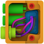
shijan Posted February 22, 2017 Author Share Posted February 22, 2017 and some final renders of the box body Quote Link to comment Share on other sites More sharing options...
shijan Posted February 27, 2017 Author Share Posted February 27, 2017 THE MASTER COPY! This is printed on B9Creator DLP 3D printer. tweak 1 Quote Link to comment Share on other sites More sharing options...
tweak Posted February 28, 2017 Share Posted February 28, 2017 This is looking epic! Quote Link to comment Share on other sites More sharing options...
shijan Posted March 1, 2017 Author Share Posted March 1, 2017 I want to believe that adapter will be available in the middle-end of the March. If someone potentially interested in this adapter just pm or email me and i'll add you to the customers list. This helps me to understand how many copies to produce in first batch and send them all together without delay. Quote Link to comment Share on other sites More sharing options...
shijan Posted March 15, 2017 Author Share Posted March 15, 2017 OK people, some news here: After long research i dropped the concept of DIY silicone molding and plastic casting because it appears too complicated, requires a lot of additional gear, results are not always predictable, and experiments may take many months. Also i find that those plastic casting materials are not too heat resistant and can deform under extreme sun. It is also problematic to get a neutral deep black color with them. So i return to concept of 3D printed box. I tested few different FDM 3D printers and find that they can produce very different results depending of used material and printer brand. Also instead of unpredictable fragile ABS plastic i find Elastan D70 - new industrial material developed by local manufacturer. It is solid but same time slightly elastic and resistant to impact loads (95 Shore Type D). Usable in temps from -40 to +120 °С. Resistant to UV light, X-ray, wet, oils, fats and many solvents, safe for food contact, low shrinkage durable material. Internal part of the box was also redesigned. It became much stronger now. In day or so i'll get a first test sample of printed box so we can see how it looks, how it feels and do a crash test with heavy hammer. mercer 1 Quote Link to comment Share on other sites More sharing options...


Recommended Posts
Join the conversation
You can post now and register later. If you have an account, sign in now to post with your account.
Note: Your post will require moderator approval before it will be visible.